Step 6: LCD Header
Now, on the module side, it's time to attach a header to the LCD so that you can connect it to the socket from the previous section.
Tools Needed
- Soldering iron
Parts Needed
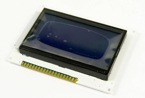
- 1 x LCD module
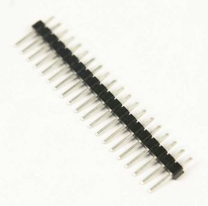
- 1 x 20-pin header
Instructions
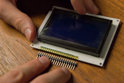
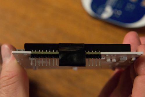
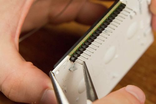
- Line up the headers with the pins on the LCD. Remember, the short side is soldered to the LCD, and the long side will extend down to meet the socket.
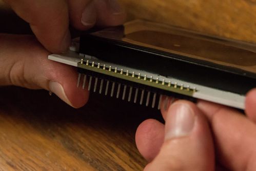
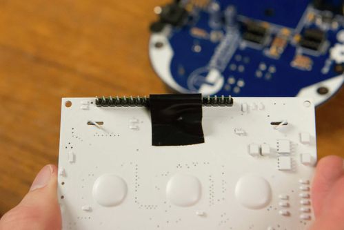
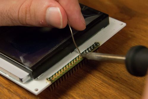
- Gently tape the header in place so that it stays upright and secure in the socket.
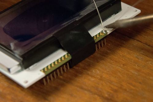
- Solder the pins on either end first.
- This process may melt the place on the header a small amount. If that happens, you can use pliers to correct any pins that might have become misaligned.
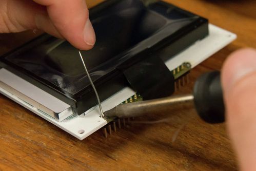
- Solder the remaining pins into place.
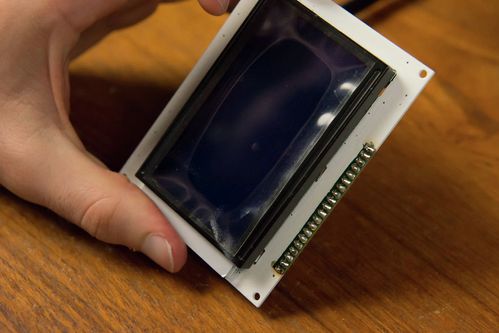
- Now you have an LCD that's ready for making awesome games!
Unless otherwise noted, content on this site is licensed under the
Creative Commons Attribution-ShareAlike 4.0 International License.
