Step 1: Comparator Socket
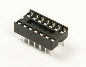
You will be installing the 14-pin DIP socket to U1. This will hold an LM339 quad comparator which compares the voltages output by the joystick to voltages from the voltage ladder.
WHAT IS A QUAD COMPARATOR?
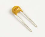
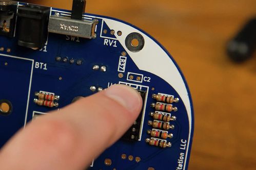
Then you will install a 0.1μF decoupling capacitor to C2.
Tools Needed
- Soldering iron
Parts Needed
- 1 x 14-pin DIP socket
- 1 x 0.1μF capacitor
Instructions
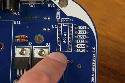
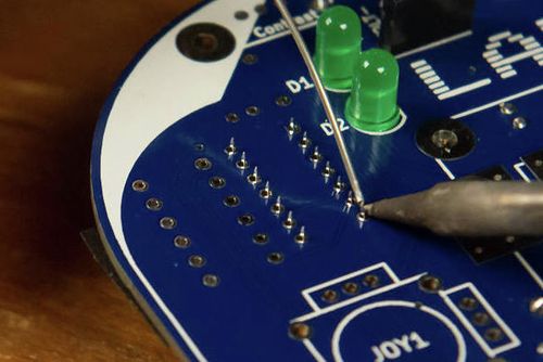
- Find the footprint for U1 on the board.
- Tape the socket across the top to hold it in place. REMEMBER: Match up the notches on the socket and the U1 footprint on the board.
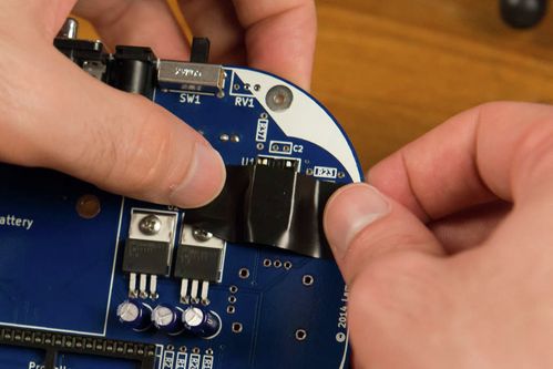
- Like with the 40-pin socket of the last section, solder two corners at opposite ends first, so you can correct any problems with positioning.
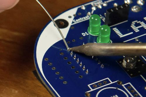
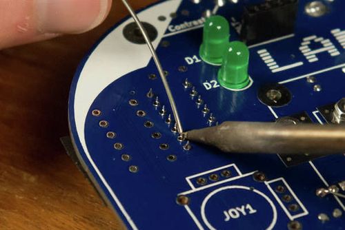
- If everything looks good, solder the rest of the pins.
- Install a 0.1μF capacitor to C2, footprint pictured.
Unless otherwise noted, content on this site is licensed under the
Creative Commons Attribution-ShareAlike 4.0 International License.
