WAITCNT
Command: Pause a cog's execution temporarily.
((PUB ┆ PRI))
WAITCNT ( Value )
- Value is the desired 32-bit System Counter value to wait for.
Explanation
WAITCNT, "Wait for System Counter," is one of four wait commands (WAITCNT, WAITPEQ, WAITPNE, and WAITVID) used to pause execution of a cog until a condition is met. WAITCNT pauses the cog until the global System Counter equals Value.
When executed, WAITCNT activates special "wait" hardware in the cog that prevents the System Clock from causing further code execution within the cog until the moment the System Counter equals Value. The
wait hardware checks the System Counter every System Clock cycle and the cog's power consumption is reduced by approximately 7/8ths during this time. In normal applications, WAITCNT may be used strategically to reduce power consumption anywhere in the program where time is wasted waiting for low-bandwidth events.
There are two types of delays WAITCNT can be used for: fixed delays and synchronized delays. Both are explained below.
Fixed Delays
Fixed delays are those that are all unrelated to one specific point in time and only serve the purpose of pausing execution for a fixed amount of time. A fixed delay, for example, may be used to wait for 10 milliseconds after an event occurs, before proceeding with another action. For example:
CON
  _clkmode = xtal1                'Set for slow crystal
  _xinfreq = 5_000_000            'Use 5 MHz accurate crystal

   repeat
     !outa[0]                     'Toggle pin 0
     waitcnt(50_000 + cnt)        'Wait for 10 ms
This code toggles the state of I/O pin P0 and waits for 50,000 system clock cycles before repeating the loop again. Remember, the Value parameter must be the desired 32-bit value to match against the System Clock's value. Since the System Clock is a global resource that changes every clock cycle, to delay for a certain number of cycles from "now" we need a value that is added to the current System Counter value. The cnt in "50_000 + cnt" is the System Counter Register variable; it returns the value of the System Counter at that moment in time. So our code says to wait for 50,000 cycles plus the current value of the System Counter; i.e.: wait 50,000 cycles from now. Assuming that an external 5 MHz crystal is being used, 50,000 cycles is about 10 ms (1/100th second) of time.
IMPORTANT: Since WAITCNT pauses the cog until the System Counter matches the given value, care must be taken to ensure that the given value was not already surpassed by the System Counter. If the System Counter already passed the given value before the wait hardware activated then the cog will appear to have halted permanently when, in fact, it is waiting for the counter to exceed 32 bits and wrap around to the given value. Even at 80 MHz, it takes over 53 seconds for the 32-bit System Counter to wrap around!
Related to this, when using WAITCNT in Spin code as shown above, make sure to write the Value expression the same way we did: in the form "offset + cnt" as opposed to "cnt + offset." This is because the Spin interpreter will evaluate this expression from left to right, and each intermediate evaluation within an expression takes time to perform. If cnt were at the start of the expression, the System Counter would be read first then the rest of the expression would be evaluated, taking an unknown amount of cycles and making our cnt value quite old by the time the final result is calculated. However, having cnt as the last value in the WAITCNT expression ensures a fixed amount of overhead (cycles) between reading the System Counter and activating the wait hardware. In fact, the interpreter takes 381 cycles of final overhead when the command is written in the form waitcnt(offset + cnt). This means the value of offset must always be at least 381 to avoid unexpectedly long delays.
Synchronized Delays
Synchronized delays are those that are all directly related to one specific point in time, a "base" time, and serve the purpose of "time-aligning" future events relative to that point. A synchronized delay, for example, may be used to output or input a signal at a specific interval, despite the unknown amounts of overhead associated with the code itself. To understand how this is different from the Fixed Delay example, let's look at that example's timing diagram.
|
|---|
Fixed Delay Timing |
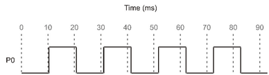
The figure above (Fixed Delay Timing) shows the output of our previous example, the fixed delay example. Notice how the I/O pin P0 toggles roughly every 10 milliseconds, but not exactly? In fact, there's a cumulative error that makes successive state changes further and further out-of-sync in relation to our start time, 0 ms. The delay is 10 ms in length, but the error occurs because that delay doesn't compensate for the length of the rest of the loop. The repeat, !outa[0] and WAITCNT statements each take a little time to execute, and all that extra time is in addition to the 10 ms delay that WAITCNT specified.
Using WAITCNT a slightly different way, for a synchronized delay, will eliminate this timing error. The following example assumes we're using a 5 MHz external crystal.
CON
  _clkfreq = xtal1               'Set for slow crystal
  _xinfreq = 5_000_000           'Use 5 MHz accurate crystal

PUB Toggle | Time
  Time := cnt                    'Get current system counter value
  repeat
    waitcnt(Time += 50_000)      'Wait for 10 ms
    !outa[0] 'Toggle pin 0
This code first retrieves the value of the System Counter, Time := cnt, then starts the repeat loop where it waits for the System Counter to reach Time + 50,000, toggles the state of I/O pin P0 and repeats the loop again. The statement Time += 50_000 is actually an assignment statement; it adds the value of Time to 50,000, stores that result back into Time and then executes the WAITCNT command using that result. Notice that we retrieved the System Counter's value only once, at the start of the example; that is our base time. Then we wait for the System Counter to equal that original base time plus 50,000 and perform the actions in the loop. Each successive iteration through the loop, we wait for the System Counter to equal another multiple of 50,000 from the base time. This method automatically compensates for the overhead time consumed by the loop statements: repeat, !outa[0] and waitcnt. The resulting output looks like the figure below (Synchronized Delay Timing).
|
|---|
Synchronized Delay Timing |
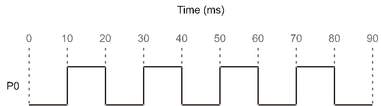
Using the synchronized delay method, our output signal is always perfectly aligned to the time base plus a multiple of our interval. This will work as long as the time base (an external crystal) is accurate and the overhead in the loop does not exceed the time interval itself. Note that we waited, with WAITCNT, before the first toggle so that the time between the very first toggle and the second matches that of all the rest.
Calculating Time
An object can delay a specific amount of time even if the application changes the System Clock frequency occasionally. To do this, use WAITCNT combined with an expression that includes the current System Clock frequency (CLKFREQ). For example, without you knowing what the actual clock frequency will be for applications using your object, the following line can be used to delay the cog for 1 millisecond; as long as the clock frequency is fast enough.
waitcnt(clkfreq / 1000 + cnt) 'delay cog 1 millisecond
For more information, see CLKFREQ.
Unless otherwise noted, content on this site is licensed under the
Creative Commons Attribution-ShareAlike 4.0 International License.
