Step 5: LCD Socket
You will be installing a 20-pin socket into P1. This is where the LCD module will connect with the board.
Tools Needed
- Soldering iron
Parts Needed
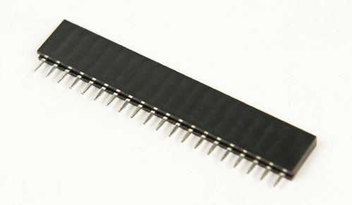
- 1 x 20-pin single-row socket
Instructions
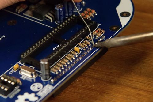
- Install the 20-pin header socket into the P1 footprint on the top side of the board.
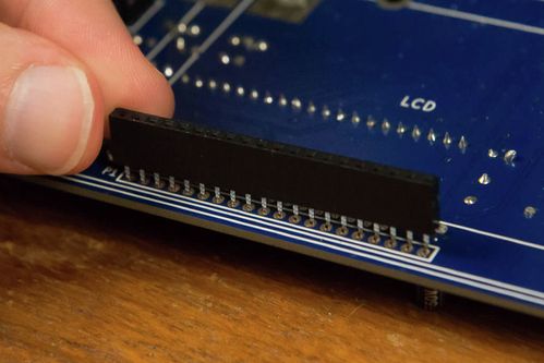
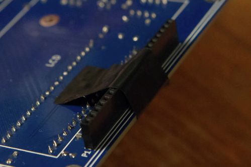
Hold it down with a piece of tape to keep it from falling out when the board is flipped.
Make sure that the header is flat against the board. This connector has to mate with the LCD and so it needs to line up just right.
- Solder the header on either end to hold it in place before soldering the rest of the pins.
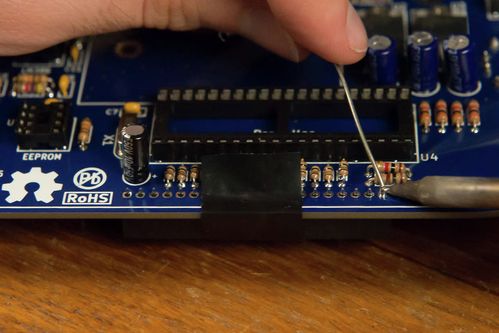

- Solder the rest of the pins.
Unless otherwise noted, content on this site is licensed under the
Creative Commons Attribution-ShareAlike 4.0 International License.
