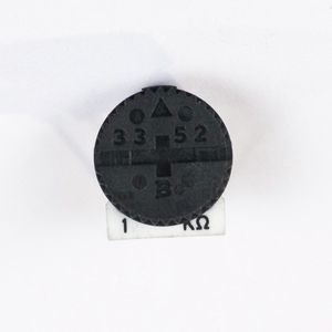
Step 2: Contrast Knob
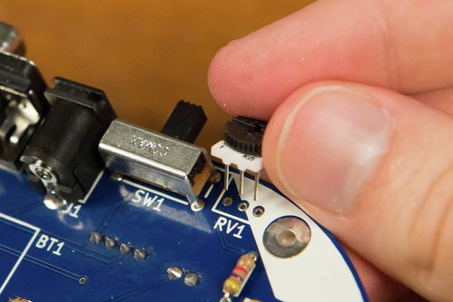
This trim pot sets a voltage between two values, and this voltage is used by the LCD internally to set the contrast.
INSERT TWO IMAGES WITH TOO DARK AND TOO HIGH CONTRASTS
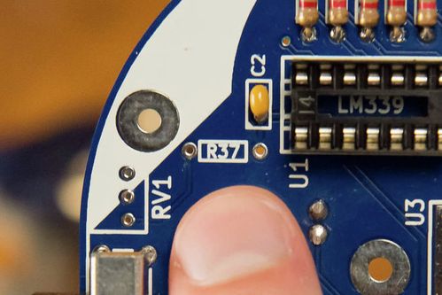
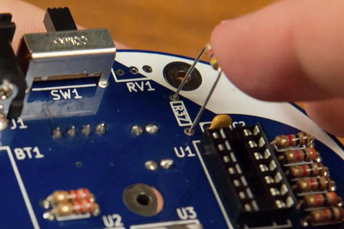
R37, R38, and RV1 set the contrast of the LCD. You'll notice that R37 is really far away from the other resistors. This is for practical reasons. This circuit runs all the way across the board so R37 is literally just somewhere along the way where it would fit. Not every design choice is a pretty one. ![]()
INSERT DIAGRAM HIGHLIGHTING TRACES AND HOW THEY TRAVERSE THE BOARD
INSERT DIAGRAM OF CONTRAST KNOB
Tools Needed
- Soldering iron
- Cutter
Parts Needed
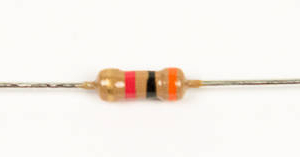
- 1 x 3kΩ resistor
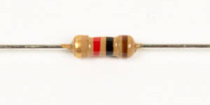
- 1 x 1kΩ resistor
- 1 x 1kΩ potentiometer
Instructions
- Solder the 3kΩ resistor into R37.
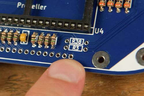
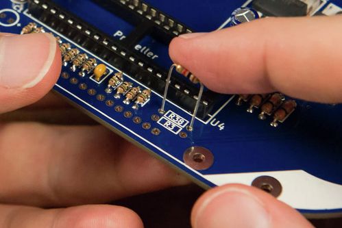
- Solder the 1kΩ resistor into R38.
- Solder the 1kΩ potentiometer into RV1.
Unless otherwise noted, content on this site is licensed under the
Creative Commons Attribution-ShareAlike 4.0 International License.
